Saturday, 22 October 2016

Assembly language program to convert hexadecimal number to BCD (for 8051 microcontroller)


Assumptions:

1. A hexadecimal number is at location 40h and we need to convert it to BCD
2. Value stored at r0 is 40h
3. At the address 40h value is FFh
4. result stored in unpacked BCD form as ones digit at r3, tens value at r2 , hundred value at r1

Before we start with actual coding lets revise about BCD

BCD is a binary representation of numbers from 0 to 9
Since there could be max 4 bit change from 0 to 9 therefor BCD could be represented by 4 bits.
9d=9h=1001 BCD

Lets back to the program,
Max 8 bit number could be FFh = 255d , So on converting any 8 bit number to bcd we have our answer upto three places ones, tens, hundred.
Answer will stored in unpacked BCD form

first three instructions are only mov instructions
first r0 is assigned a value 40h which is the address where our value (hex value to be converted into BCD) is stored 
we will get this value from memory location 40h and assign it to accumulator by instruction:
mov a, @ro 

This type of addressing is called indrect addressing where a register  stores   address of any memory location and value from that address is assigned to destination.

the above picture is showing the procedure
As our leftmost digit could at hundred place max therefore we will divide our hexvalaue by 100(decimal) = 64 (hex) instruction 4
quotient will be the leftmost value.
remainder of it is again divided by 10d=Ah
quotient will be the middle value,
remainder is again divided by 1

So we got three values at hundredth place, tens , ones would be stored at r1, r2, r3


Friday, 14 October 2016

Simple mathematic operation and switching between register banks assembely language program 8051 microcontroller

8051 Assembly Language Program to add , subtract, multiply and divide two 8 bit numbers stored in register r0 and r1 of register bank 0 , store the results of various operations in different registers of register bank 1 (without loop) 

Assumption:
Values stored at register0 , register1 of register 0 are 23 h and 0A h respectively.
h=hexadecimal
Don't get panic with program it is very easy and small


Lets start
In our operation here PSW is used to select register bank only.

As it is assumed that r0 and r1 of register bank 0 have some values. So i had put it through immediate addressing.

To perform add operation one value should be stored in accumulator. And result of addition will be in accumulator(A)
As per requirement we want to store result in register bank 1
So first we have to select register bank1

why didn't we selected register bank 0 before?
Because on resetting the value of PSW register =00h means all bits are zero. Therefore automatically register bank zero get selected.


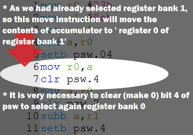
 As we had selected register bank 1 , now we could transfer the contents of accumulator(A) to register 0 of register bank 1. 
mov r0,a


To perform other arithmetic operation we need the value of register bank 0 therefore again we selected register bank 0. This is done by making 4th bit of PSW(PROGRAM STATUS WORD) again zero
Similary other mathematic operation will perform.


After first clr psw.4 rest of maths operation is performed as it is 

Subb a,r1 
Above instruction will minus contents of r1 from contents of accumulator

   Accumulator
-  value at register 1 of register bank 0
---------------------------------------------------
   result

Mul AB
 instruction for multiplication will multiply two 8 bit numbers stored in A(accumulator) and register 'B' and 16 bit result again get stored into A(lower byte of result) , B(higher byte of result)

Add  operation only


Sunday, 21 August 2016

Bytewise and bitwise operation difference

Before we start Bytewise and bitwise operation we should know what is bit and Byte
1 Byte consists of 8 bits
              8 bit = 1Byte
              4 bit = 1 nibble


Bytewise operation

8085 microprocessor or some other microcontroller or microprocessor performs only bytewise operation . By Bytewise operation i mean , all 8 bits of 1 byte would get change no matter we want to change single bit.

For example: In 8085 microprocessor we have to perform either Oring or Anding of byte to change a particular bit.
Suppose in accumulator the value is 22h or 00100010b and if we want to reset (0) 5th bit we have to perform either Oring or Anding whole Byte.

On writing instruction
ANI dfh

following operation will perform

at accumulator:            00100010 b   = 22h
intermediate walue:      11011111 b   = DFh
result:                         00000010 b   = 02h

** b means binary
** h means hexadecimal
**anding
    0 and 0=0
    0 and 1=0
    1 and 0=0
    1 and 1=0


U might have seen the school benches. When the boy at middle wants to go the other corner boy also have to move.

Similarly if we want to change single bit we have to mask all 8 bits of 1 Byte.


Bitwise Operation

bit means either 1 or 0. In this type of operation we can set (1) or reset (1) a single bit. Now to set a particular bit we should know the address of that bit.
In some microcontroller like 8051 there is facility of bit addressable area where we could set or reset a particular bit. We don't need to mask whole Byte.

For example in 8051 microcontroller to set(1) a particular bit there is an instruction
SETB  bit

to reset
CLR bit


U might have seen the table which could fold. So now if middle student wants to move he could without disturbing his benchmates.


In bitwise operation single bit could change.

Thank u 4 vising my blog


Wednesday, 22 June 2016

Procedure of circular convolution

Circular Convolution

if u like step by step learning. This post could help. Thank u for visiting my blog

solving circular convolution is just like solving graphical linear convolution.

three easy steps:
1. Fold
2. Shift 
3. Multiply 
And get the answers

Let the two sequences be x1(n)={1, 1, 2, 2}
x2(n)={1, 2, 3, 4}


for x(-n) enter the elements in counter clockwise direction. Multiply it to x2(n). Don't change x2(n). The result u will get after element by element multiplication and adding all the elements of result will be x3(0). You can check it by formula.


Then rotate the ring by 1 unit in clockwise direction. It will be x1(1-n). Multiply x1(1-n) by x2(n). Remember x2(n) will not change. The result after multiplication and adding all the elements of result is x3(2).

same will happen with x1(2-n) and x1(3-n)

Therefore the result is
x3(n)={15, 17, 15, 13}

Friday, 3 June 2016

Linear convolution

Graphical Linear convolution
i m writing in msg language. Its true muje convolution smjne me bhut problem ayi. And even didn't get it for 3 sem . 
lets start. Take two signals x(n) and h(n). We can vertically fold any of the two signals. Consider h(n).  But notice we have to fold by k not n 
therefore we take a dummy variable k. This i shown in the picture below. Now we can fold. Or take the mirror image of h(k). This also i had shown.
Now we multiply x(k) with h(-k) point to point multiplication.

now shift h(-k) by 1 rightwards. This would be h(1-k). Now again multiply h(1-k) by x(k). The result would be y(1). Similarly do with h(2-k) , h(3-k) and so on to give y(2), y(3).

so we obtain y(0), y(1),..………
and now y(n)={y(0), y(1),……………}

i m attaching a video becoz i didn't get folding and shifting easily.so that is my visualization

Program to solve 4 variable equation(octave code)

function [x,y,z,alpha]=eq4variable( aaaa1,bbbb1,dddd1,eeee1,cccc1,aaaa2,bbbb2,dddd2,eeee2,cccc2,aaaa3,bbbb3,dddd3,eeee3,cccc3,aaaa4,bbbb4,d...